- 您现在的位置:买卖IC网 > Sheet目录3871 > PIC18F85J50T-I/PT (Microchip Technology)IC PIC MCU FLASH 16KX16 80TQFP
Philips Semiconductors
Product data
P87LPC767
Low power, low price, low pin count (20 pin)
microcontroller with 4-kbyte OTP and 8-bit A/D converter
2002 Mar 25
30
Low Voltage EPROM Operation
The EPROM array contains some analog circuits that are not
required when VDD is less than 4 V, but are required for a VDD
greater than 4 V. The LPEP bit (AUXR.4), when set by software, will
power down these analog circuits resulting in a reduced supply
current. LPEP is cleared only by power-on reset, so it may be set
ONLY for applications that always operate with VDD less than 4 V.
Reset
The P87LPC767 has an integrated power-on reset circuit which
always provides a reset when power is initially applied to the device.
It is recommended to use the internal reset whenever possible to
save external components and to be able to use pin P1.5 as a
general-purpose input pin.
The P87LPC767 can additionally be configured to use P1.5 as an
external active-low reset pin RST by programming the RPD bit in the
User Configuration Register UCFG1 to 0. The internal reset is still
active on power-up of the device. While the signal on the RST pin is
low, the P87LPC767 is held in reset until the signal goes high.
The watchdog timer on the P87LPC767 can act as an oscillator fail
detect because it uses an independent, fully on-chip oscillator.
UCFG1 is described in the System Configuration Bytes section of
this datasheet.
SU01359
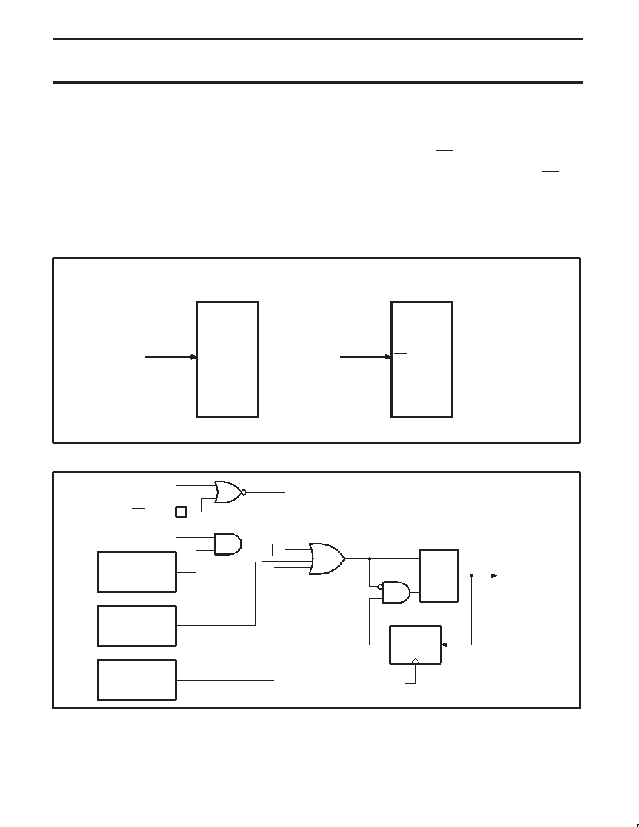
87LPC767
P1.5
Pin is used as
digital input pin
Internal power-on
Reset active
UCFG1.RPD = 1 (default)
RST
Pin is used as
active-low reset pin
Internal power-on
Reset active
UCFG1.RPD = 0
Figure 22. Using pin P1.5 as general purpose input pin or as low-active reset pin
SU01170
CHIP RESET
CPU
CLOCK
Q
RESET
TIMING
RPD (UCFG1.6)
WDT
MODULE
SOFTWARE RESET
SRST (AUXR1.3)
POWER MONITOR
RESET
RST/VPP PIN
WDTE (UCFG1.7)
S
R
Figure 23. Block Diagram Showing Reset Sources
发布紧急采购,3分钟左右您将得到回复。
相关PDF资料
PIC18F45J10-I/P
IC PIC MCU FLASH 16KX16 40DIP
PIC24FJ16GA002-I/SO
IC PIC MCU FLASH 16K 28-SOIC
PIC18F25K22-I/SO
MCU 8BIT 32KB FLASH 5.5V 28SOIC
PIC18F26K20-I/SS
IC PIC MCU FLASH 32KX16 28-SSOP
PIC24F08KA102-I/ML
IC PIC MCU FLASH 8K 28-QFN
PIC18F84J90T-I/PT
IC PIC MCU FLASH 8KX16 80TQFP
PIC18F2321T-I/SS
IC PIC MCU FLASH 4KX16 28SSOP
PIC18F2221T-I/SS
IC PIC MCU FLASH 2KX16 28SSOP
相关代理商/技术参数
PIC18F85J90-I/PT
功能描述:8位微控制器 -MCU 32KB Flash 2048BRAM 67I/O RoHS:否 制造商:Silicon Labs 核心:8051 处理器系列:C8051F39x 数据总线宽度:8 bit 最大时钟频率:50 MHz 程序存储器大小:16 KB 数据 RAM 大小:1 KB 片上 ADC:Yes 工作电源电压:1.8 V to 3.6 V 工作温度范围:- 40 C to + 105 C 封装 / 箱体:QFN-20 安装风格:SMD/SMT
PIC18F85J90T-I/PT
功能描述:8位微控制器 -MCU 32KB Flash 2048bytes-RAM 67I/O RoHS:否 制造商:Silicon Labs 核心:8051 处理器系列:C8051F39x 数据总线宽度:8 bit 最大时钟频率:50 MHz 程序存储器大小:16 KB 数据 RAM 大小:1 KB 片上 ADC:Yes 工作电源电压:1.8 V to 3.6 V 工作温度范围:- 40 C to + 105 C 封装 / 箱体:QFN-20 安装风格:SMD/SMT
PIC18F85J94-I/PT
制造商:Microchip Technology Inc 功能描述:80 PINS, 32KB FLASH, 4KB RAM, 16MIPS, NANOWATT XLP, LCD, USB - Trays
PIC18F85J94T-I/PT
制造商:Microchip Technology Inc 功能描述:80 PINS, 32KB FLASH, 4KB RAM, 16MIPS, NANOWATT XLP, LCD, USB - Tape and Reel 制造商:Microchip Technology Inc 功能描述:IC MCU 8BIT 32KB FLASH 80TQFP 制造商:Microchip Technology Inc 功能描述:8-bit Microcontrollers - MCU 80 pins, 32KB Flash, 4KB RAM, 16MIPS 制造商:Microchip Technology Inc 功能描述:80 pins, 32KB Flash, 4KB RAM, 16MIPS, nanoWatt XLP, LCD, USB, 80 TQFP 12x12x1mm
PIC18F85K22-E/PT
功能描述:8位微控制器 -MCU 32KB Flash 2KB RAM
RoHS:否 制造商:Silicon Labs 核心:8051 处理器系列:C8051F39x 数据总线宽度:8 bit 最大时钟频率:50 MHz 程序存储器大小:16 KB 数据 RAM 大小:1 KB 片上 ADC:Yes 工作电源电压:1.8 V to 3.6 V 工作温度范围:- 40 C to + 105 C 封装 / 箱体:QFN-20 安装风格:SMD/SMT
PIC18F85K22-I/PT
功能描述:8位微控制器 -MCU 32kB Flash 2kB RAM
RoHS:否 制造商:Silicon Labs 核心:8051 处理器系列:C8051F39x 数据总线宽度:8 bit 最大时钟频率:50 MHz 程序存储器大小:16 KB 数据 RAM 大小:1 KB 片上 ADC:Yes 工作电源电压:1.8 V to 3.6 V 工作温度范围:- 40 C to + 105 C 封装 / 箱体:QFN-20 安装风格:SMD/SMT
PIC18F85K22-I/PTRSL
功能描述:8位微控制器 -MCU 32KB Flash 2KB RAM nanoWatt XLP GP RoHS:否 制造商:Silicon Labs 核心:8051 处理器系列:C8051F39x 数据总线宽度:8 bit 最大时钟频率:50 MHz 程序存储器大小:16 KB 数据 RAM 大小:1 KB 片上 ADC:Yes 工作电源电压:1.8 V to 3.6 V 工作温度范围:- 40 C to + 105 C 封装 / 箱体:QFN-20 安装风格:SMD/SMT
PIC18F85K22T-I/PT
功能描述:8位微控制器 -MCU 32kB Flash 2kB RAM
RoHS:否 制造商:Silicon Labs 核心:8051 处理器系列:C8051F39x 数据总线宽度:8 bit 最大时钟频率:50 MHz 程序存储器大小:16 KB 数据 RAM 大小:1 KB 片上 ADC:Yes 工作电源电压:1.8 V to 3.6 V 工作温度范围:- 40 C to + 105 C 封装 / 箱体:QFN-20 安装风格:SMD/SMT